Innovations from the Zimmer Group
Innovations from our technology areas
Long-stroke axes
LINEAR DRIVES FOR YOUR PROCESSES
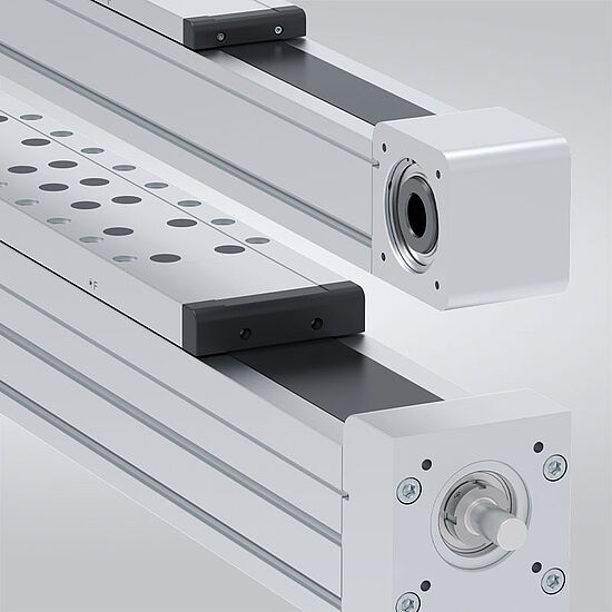
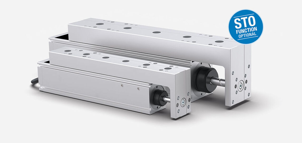
These new long-stroke axes from the AMB and AMS series from the Zimmer Group set new benchmarks in automation technology. While the long-stroke axis with toothed belt drive of the AMB series excels with high dynamics and speed, the long-stroke axis with ball screw drive of the AMS series features maximum precision and high feed forces. The long-stroke axes can be ordered to the nearest millimeter. Options such as an integrated clamping element, a cover strip for adverse environmental conditions and a complete drive train including clutches, gearboxes, motors and drive control systems are also available.
Your benefits:
- High force and moment capacity thanks to optimized axis profile and integrated recirculating ball bearing guide
- Optional drive train consisting of a clutch, gearbox, motor, drive control system and other accessories
- Maximum movement speeds with optional spindle support
- Short cycle times with speeds of up to 5 m/s and acceleration of up to 50 m/s²
- Optionally integrated clamping element for high clamping forces without interference contours
AC SERIES COMPACT AXES
LINEAR DRIVE FOR YOUR PROCESSES
MAXIMUM PERFORMANCE IN MINIMAL SPACE
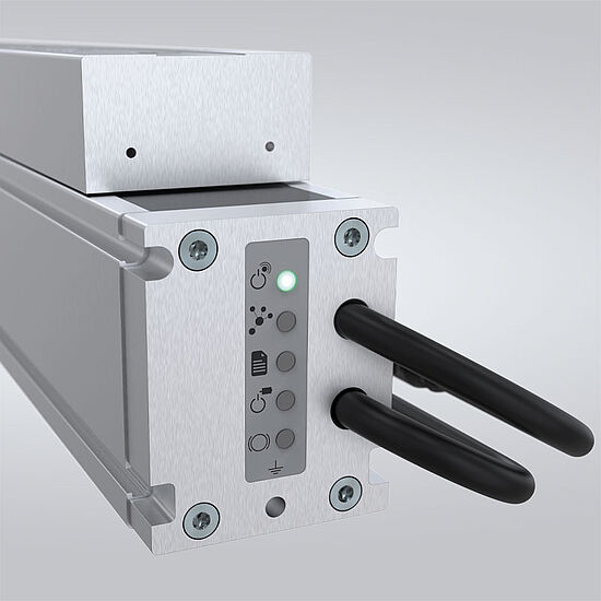
The space-saving design of the AC series enables a high level of manufacturing flexibility and efficiency in the most varied application areas. It combines precise linear movement with powerful, integrated drives – and in a tiny amount of space. This allows it to be easily integrated into existing systems and combined together without problems. It thus increases the cost-effectiveness and performance of your automated processes. High speed and rapid acceleration also mean that you do not have to make any compromises in performance, even in tight space conditions.
OUR EXPERTISE – YOUR ADVANTAGES
- Optionally with safe torque off function
- Flexible control with IO-Link or CANopen
- Fast and powerful thanks to ball screw with BLDC motor
- High load capacity and service life thanks to linear guide with double rail carriage
| Technical data | ||||
|---|---|---|---|---|
| Series | ACS40 | ACS60 | ||
| Stroke [mm] | 100 | 150 | ||
| Feed force max. [N] | 170 | 270 | ||
| Speed max. [m/s] | 0.8 | 1,0 | ||
| Acceleration max. [m/s2] | 20 | 17 | ||
| Repeat accuracy +/- [mm] | 0.01 | 0.01 | ||
Tool changer
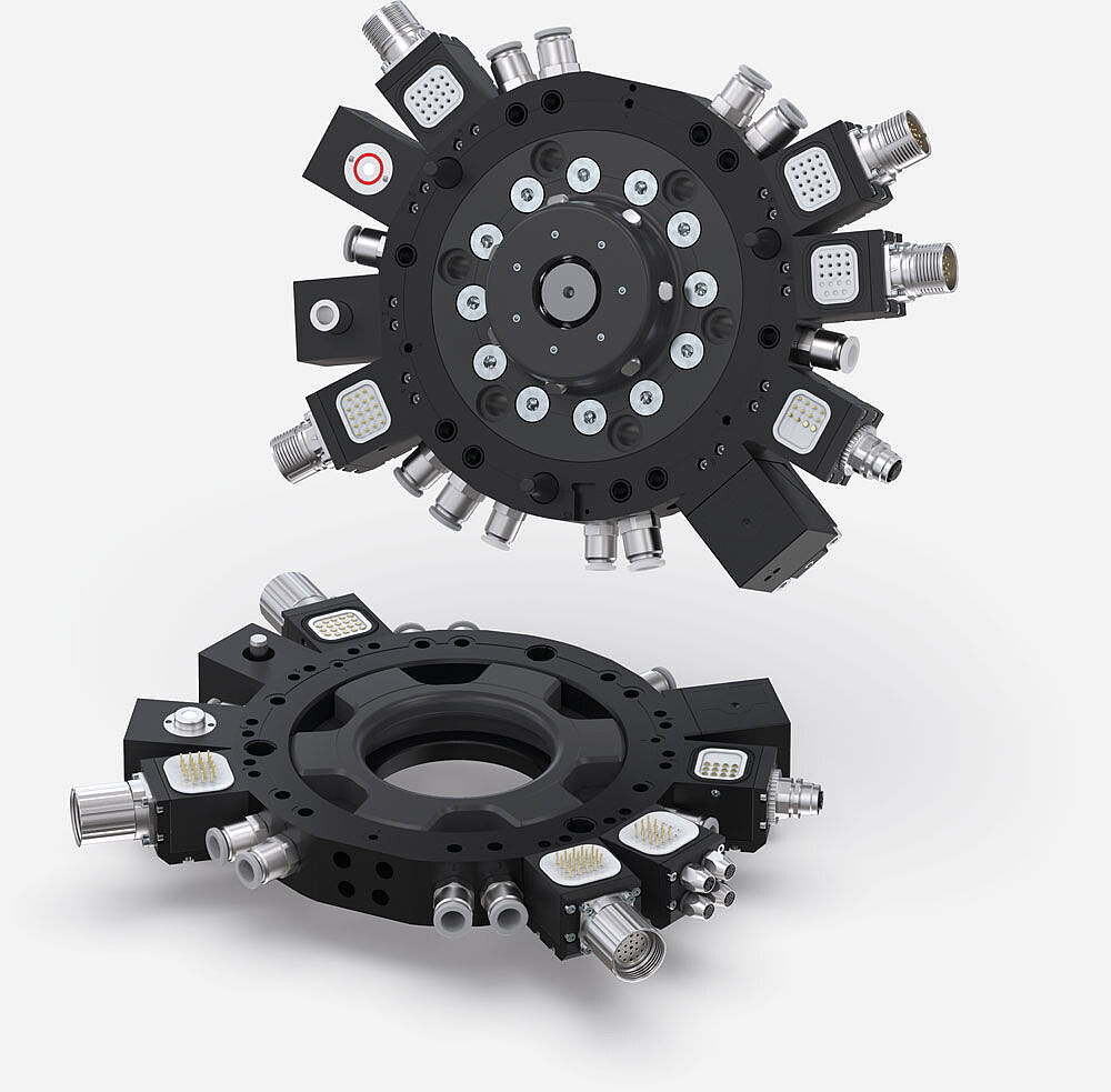
WPR5000 series
NEW TOOL CHANGER SERIES FOR ALL INDUSTRIES
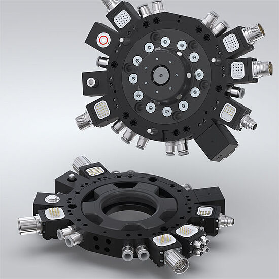
The new WPR5000 tool changer series is characterized by a flat design and, depending on the installation size and application, can carry high payloads of over 500 kg. The tool changer has been specially developed for demanding applications where high repeatability and maximum service life are essential. The WPR5000 offers maximum flexibility for a wide range of applications thanks to the wide variety of installation sizes. Up to ten integrated pneumatic pass through ports ensure reliable compressed air and vacuum transmission with large cross-sections, while an endless variety of other energy elements can be optionally selected for other requirements (load current, signal current, hydraulics and communication).
PHARMA TOOL CHANGER
Aseptic standard product
Satisfies the highest hygiene requirements
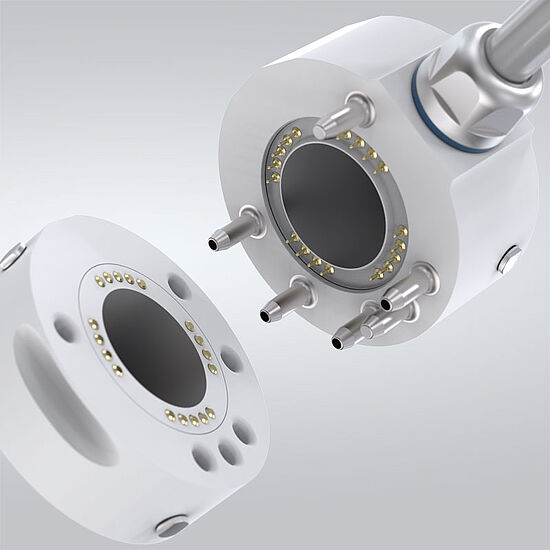
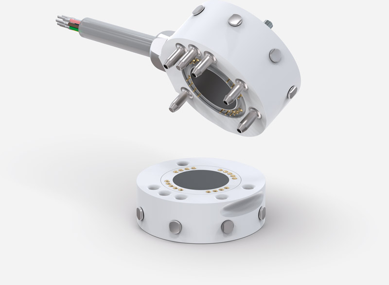
The new tool changer from Zimmer Group features a hygienic, FDA-compliant design and meets the requirements of protection class IP67. The housing is made of easy-to-clean PET and is hydrogen peroxide resistant, making it ideal for use in hygienically sensitive areas. Up to four fluid carriers are supported.
The innovative use of materials means that It is extremely light and compact. The magnetic tool changer enables the fast and easy exchange of batch parts. A permanent electromagnet ensures that the tool and workpiece remain connected reliably, even when the electricity fails – a key safety feature.
| Technical data | ||||
|---|---|---|---|---|
| Pharma tool changer | WMR2063F-00-A, WMR2063L-00-A, AWMR2063-00-A | |||
| Tightening force [N] | 250 | |||
| Handling weight [kg] | Up to 10 | |||
| Protection class in accordance with IEC 60529 | IP67 | |||
| Repeat accuracy +/- [mm] | 0.02 | |||
| Nominal current [A] | 3 | |||
| Nominal voltage [V] | 24 | |||
| Operating temperature [°C] | 5... +80 | |||
UL CERTIFICATION
GEH6000IL UND GED6000IL ZERTIFIZIERT FÜR DEN NORDAMERIKANISCHEN MARKT
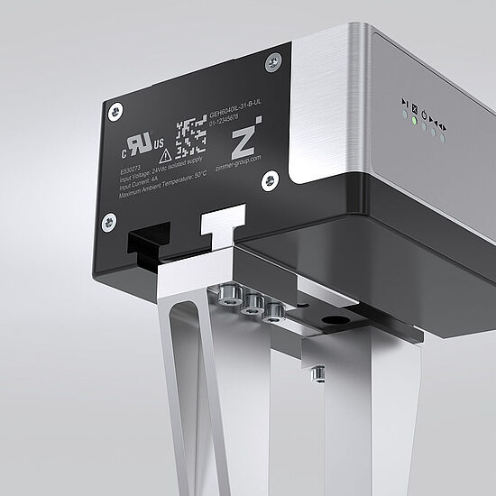
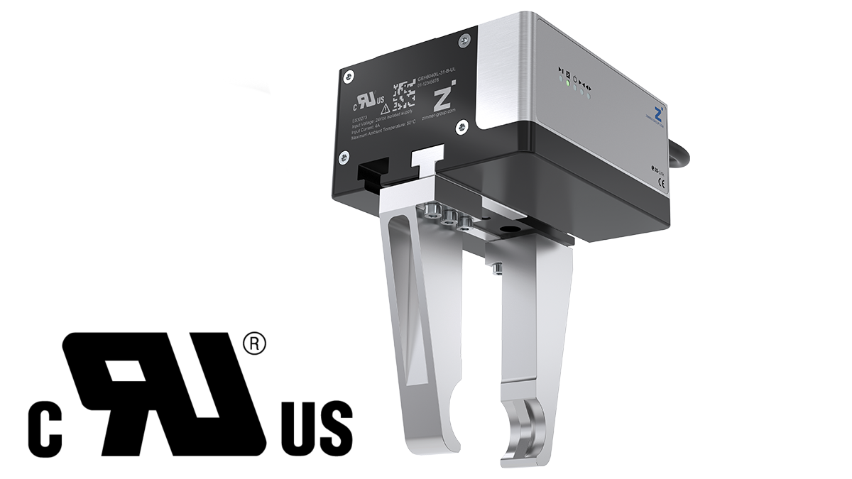
The 6000 product family is the first gripper series worldwide to be UL-certified, ensuring not only the highest safety standards, but also compliance with North American regulations. This simplifies project planning and machine acceptance, saves time and money and ensures that our components operate smoothly in production plants. This certification gives you a clear competitive advantage: maximum security, increased efficiency and confidence in the quality of our solutions.
Zimmer Systems
Solutions for a huge range of industries
Experienced automation partner
With more than 40 years of experience in system solutions, we have established ourselves as a trusted and reliable automation partner for our customers. 140 employees continuously develop and integrate sustainable application solutions and automation concepts for all industries with state-of-the-art machines. For optimized productions rates and the highest quality standards.
EOAT for tires, wheels and rims
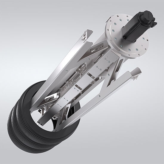
Zimmer Systems has exceptional expertise in the development, manufacture and integration of EOATs for handling tires, wheels and rims. With our experience and more than 5,000 hours of development work, we have been a reliable partner for end customers and equipment manufacturers in the tire industry since 2008. Our standardized gripper systems set new industry standards.
Battery handling – e-mobility solutions
We are leaders in the development of battery handling solutions for e-mobility. With more than 100,000 development hours since 2014, we are a trusted development partner for premium automobile manufacturers, OEMs and system manufacturers. Our tailored solutions ensure efficient and reliable automation in the battery manufacturing value chain.
Logistics and woodworking
TAILORED TO SPECIFIC APPLICATIONS
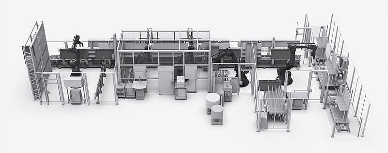
FURNITURE FRONT PROCESSING | BATCH SIZE 1 ROBOT-SUPPORTED DRILLING SOLUTIONS
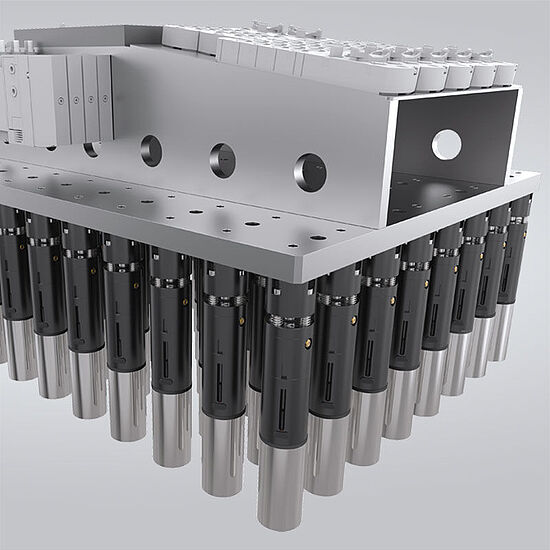
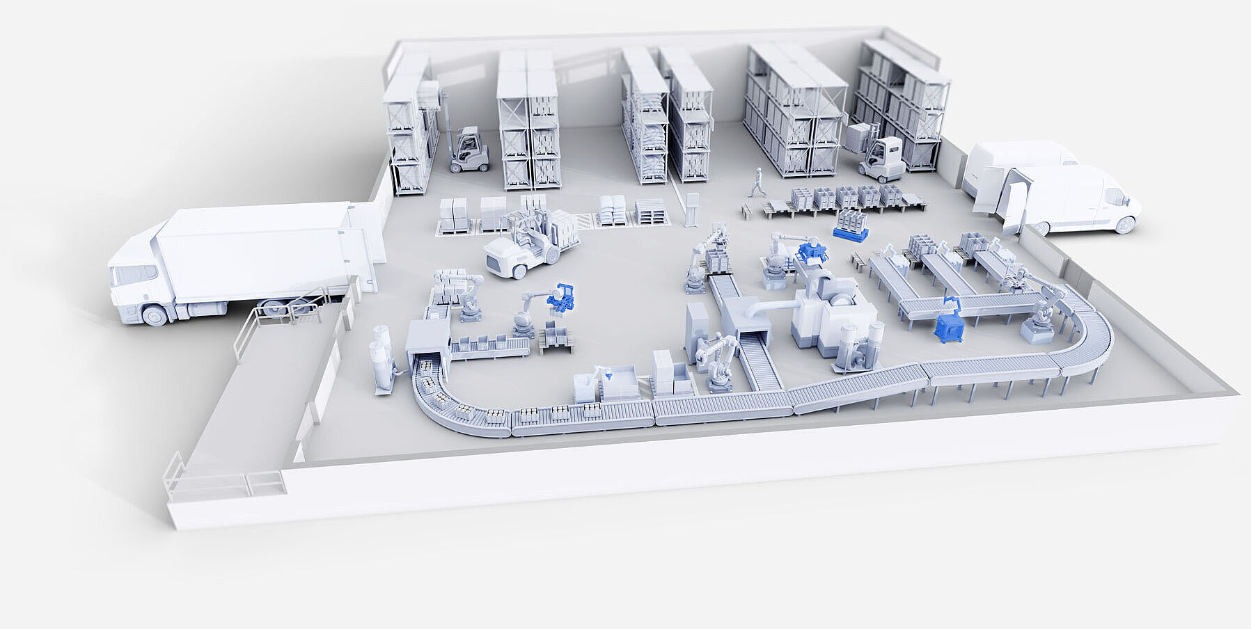
Highly flexible shuttle circulation meets precision-compensated industrial robots with a drilling head for 17 vertical spindles and a buffer unit. Automatic loading and unloading is integrated into the customer's production control system.
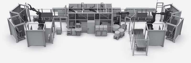
Furniture front processing system with shuttle circulation, precision-compensated industrial robots, a drill head with 17 vertical spindles, a milling spindle and a buffer adjustment device. The automatic loading and unloading of furniture fronts in shelf trolleys with safe shuttle storage ensures non-stop production.
Logistics solutions: Sorting and decoupling cells
This logistics system enables the automatic storage of manually stacked parts as well as the identification and control of the workpieces on the central conveyor belt. The parts are distributed efficiently across three identical storage cells to balance the load before being transported to the next process step.

Tires, wheels and rims
Gripper systems
Handling systems from the experts
Tire manufacturing is a complex process that involves many steps from the green tire right through to the finished tire and rim. With increasing automation, we provide a wide range of handling solutions for different processes and production steps. The Zimmer Group has already realized a large number of projects. Our portfolio includes around 200 grippers and 15 standard grippers for the tire, wheel and rim industry.

| Technical data | ||||
|---|---|---|---|---|
| Tire type | Motorbike | PCR (Passenger Cars Radial Tires) | TBR (Trucks and Bus Radial Tires) | |
| Outer diameter max. [mm] | 720 | 900 | 1250 | |
| Outer diameter min. [mm] | 385 | 450 | 780 | |
| Inner diameter max. [mm] | 520 (20") | 685 (27") | 710 (28") | |
| Inner diameter min. [mm] | 204 (8") | 304 (12") | 450 (18") | |
| Height max. [mm] | 215 | 400 | 460 | |
| Height min. [mm] | 60 | 135 | 200 | |
| Weight max. [kg] | 18 | 45 | 100 | |
| Weight min. [kg] | 1,4 | 4 | - | |
| Parts size variance | 8" - 20" | 12" - 27" | 18" - 28" | |
EOAT solutions for batteries
Magnetic gripper
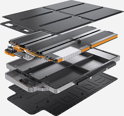
SOLUTIONS FOR BATTERY MANUFACTURING
The Zimmer Group is a development and system partner to major-name premium manufacturers and system manufacturers in battery production for electric vehicles. Whether for the production of cylindrical, prismatic or pouch cells. In partnership with you, we will develop the right solution – from the cell, through the packaging, right up to the module.
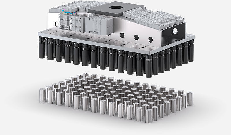
MAGNETIC grippers for cylindrical cells
The gripping of cylindrical cells requires precision interplay between the individual cells. The Zimmer Group has taken its standard magnetic gripper and developed a compact and powerful end-of-arm tool that holds the cells securely with a holding force of 65 N, even during high accelerations and emergency stops. With a low residual holding force of less than 1 N with deactivated magnets, the HPM2046 gripper ensures reliable set-down.
FAST ROUTES
INTRALOGISTICS SOLUTION
In a constantly changing world, companies are faced with the challenge of optimizing their intralogistics processes.
Our customized automation solutions ensure seamless integration into existing processes
and give you a real competitive advantage.
Bag gripper
Industry standard
HANDLING SYSTEM FOR BAGS
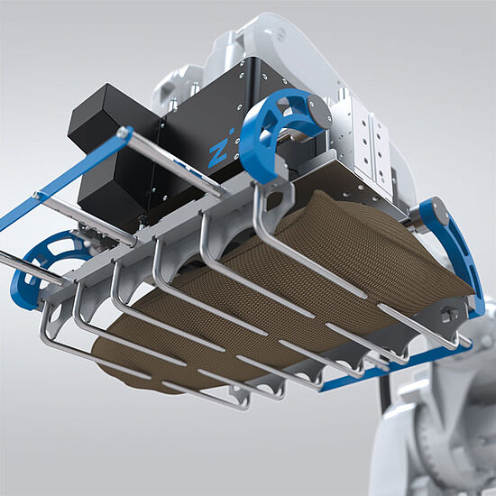
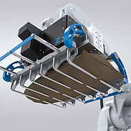
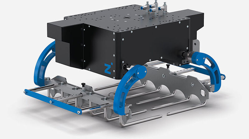
The Zimmer Group bag gripper is a one-of-a-kind end-of-arm system for handling bags filled with a wide variety of products. These include flour, fruit, vegetables, grain, fertilizer, chemicals, cement or numerous other products. At the same time, the materials of the bags to be handled also vary, including paper, plastic, jute and (woven) fabric.
PRODUCT ADVANTAGES
- Synchronous, pneumatically operated jaw movement and force conservation hold the workpiece centered and ensure long service life
- Large drive cylinders for fast cycle times of up to 20 cycles per minute depending on robot and travel path
- Optional functions such as lay-flat, intermediate layer handling and pallet handling
- Special forks for foodstuffs and hazardous/chemical materials
- Palletizing and depalletizing software for Yaskawa/ABB robots available
| Technical data | ||||
|---|---|---|---|---|
| Part number | BAG137256 | BAG137855 | Z01SYS165171 | |
| Product | Bag gripper | Bag gripper | Double bag gripper | |
| Max workpiece weight [kg] | 25 | 50 | 25 + 25 | |
| System weight [kg] | 45 | 55 | 115 | |
| Dimensions max. [mm] [l x w x h] | 600 x 170 x 75 | 700 x 500 x 175 | 600 x 170 x 75 + 600 x 430 x 150 | |
| Dimensions min. [mm] [l x w x h] | 600 x 170 x 75 | 700 x 300 x 100 | 600 x 170 x 75 + 600 x 170 x 75 | |
| Open/closing time [s] | 0.6 | 0.6 | 0.6 | |
MILES
AUTONOMOUS MOBILE ROBOT
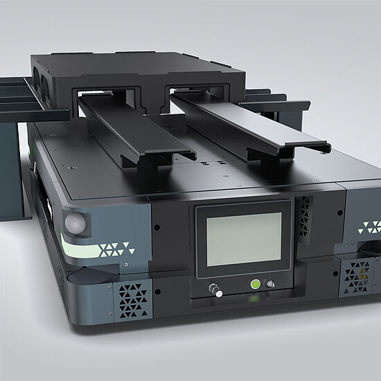
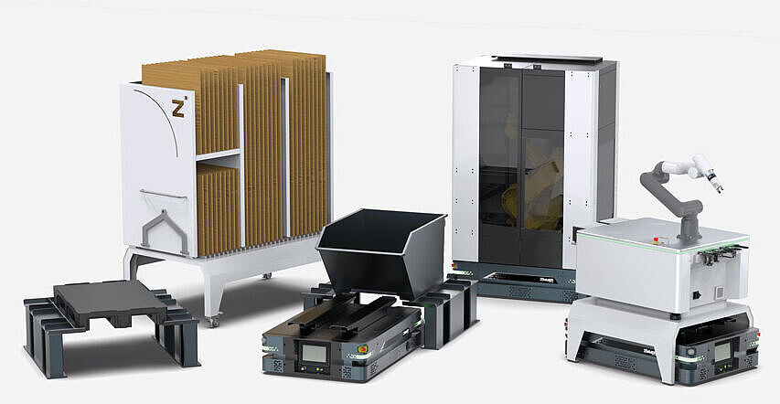
INDIVIDUAL, DRIVERLESS TRANSPORT SYSTEMS FOR PRODUCTION AND LOGISTICS PROCESSES
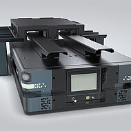
In recent years, autonomous mobile robots (AMRs) have developed into a revolutionary force that has transformed industries and redefined efficiency in many different sectors. AMRs are intelligent, self-navigating machines
that are designed to perform tasks without direct human intervention.
They combine state-of-the-art technologies and modern sensors to navigate complex environments, interact with objects and perform tasks with precision.
OUR EXPERTISE – YOUR ADVANTAGES
Maximum availability
- Best view of the work area at all times
- Collaborative cooperation – human and machine in one system
Modular concept with free layout design
- No need for protective housing
- Interface for setting up different modules possible
- Subsequent integration into existing processes possible
Simple extension of the automation system
- Additional AMRs can be integrated into the system later
Complete system comprising hardware, software and servicing
- Complete integration into the entire production process, with control architecture from a single source
- Comprehensive system overview with powerful master computer
- Intelligent navigation and fleet management: Reprogramming of the AMR travel paths possible at any time
ZiMo
THE SOLUTION-ORIENTED ROBOT CELL
FLEXIBLE AND MOBILE PROCESS AUTOMATION
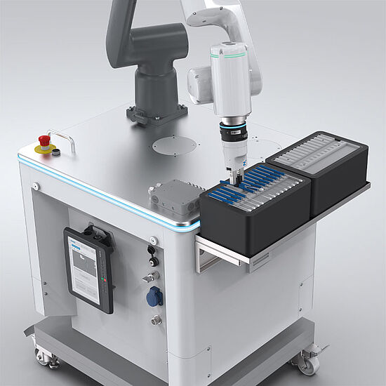
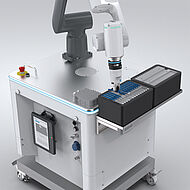
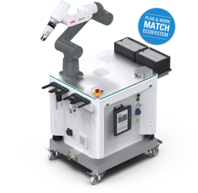
ZiMo is a cost-effective and simple option for automating processes for small, medium and variable batch sizes. The flexible robot cell from the Zimmer Group features fast commissioning and intuitive operation and makes the introduction to automation fast and uncomplicated.
Whether you want to carry out installation work, pick-and-place tasks or training courses – ZiMo is perfect for you. You can freely select from a variety of accessory parts and then receive a customized complete package that corresponds to your requirements. Interested? We would be happy to advise you!
OUR EXPERTISE – YOUR ADVANTAGES
- Flexibility at the point of use: Compact size enables free and mobile positioning in the system.
- Intuitive operation: Easy commissioning and convenient operation via the robot-independent human-machine interface (HMI).
- Boost productivity and quality: Cost-effective acquisition and fast integration optimize your production processes.
- Variable configuration: Choose from a wide range of accessories, tailored to your specific requirements.
FLEXIBLE CONFIGURATION
Compatible with the leading robot manufacturers – select from a comprehensive range of accessories: Gripper and vacuum systems, sensor technology, MATCH robot module and other components. Should the requirements in your production process change, you can adapt ZiMo in accordance with your specific requirements quickly and without great effort or cost. The versatile workstation setup and compact size make ZiMo a reliable robot cell for almost any application.
ZiMo PHARMA VERSION
With specially sealed robot technology such as an aseptic tool changer and a large portfolio of cleanroom grippers, you remain flexible even under demanding working conditions. Ideal protection against contamination meets maximum precision when handling pharmaceutical substances.
MULTI-ITEM GRIPPER
VACUUM SUCTION CUP AND PARALLEL GRIPPER
Universal GRIPPER WITH object RECOGNITION
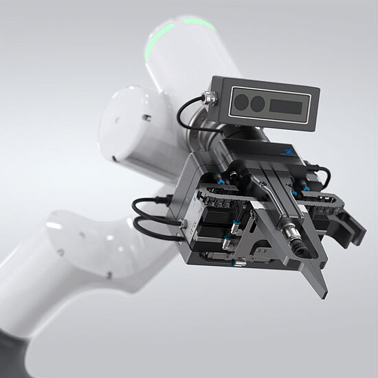
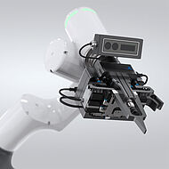
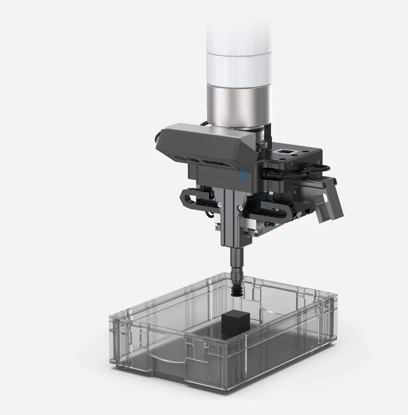
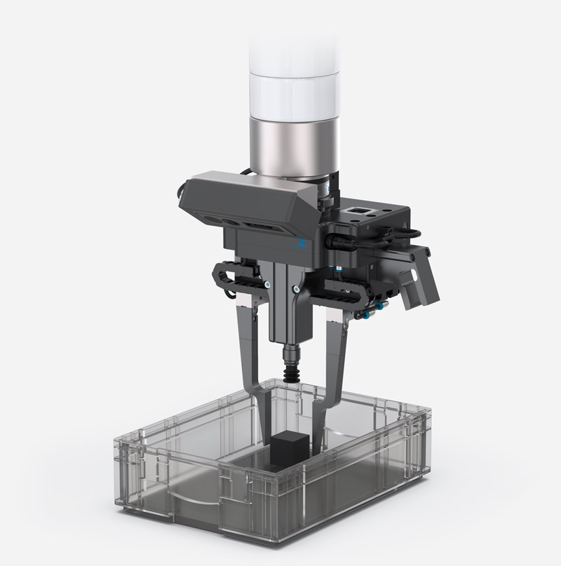
The Multi-item gripper combines a mechanical gripper and a vacuum gripper in one end effector. AI-supported image recognition and intelligent software take your bin picking tasks to the next level!
Vacuum gripper
The advantages of the gripper are particularly evident in bin picking with different surfaces and unsorted parts. The vacuum gripper is equipped with a vacuum maintenance system that ensures energy-efficient operation. The reliable medium supply and stable cylinder guidance enable precision applications, even with a wide variety of workpieces. Thanks to the interchangeable suction cups, you are ideally equipped for flexible tasks.
Parallel grippers
The vacuum gripper is complemented by a standard component that enables reliable and safe gripping. Thanks to URCap, installation and commissioning are just as easy as controlling the gripper. With extensive experience in handling technology, we have the expertise to tailor the gripper fingers to individual requirements.
CLEANROOM CERTIFICATIONS
PRODUCTS WITH CLASSIFICATION
TÜV-CERTIFIED AUTOMATION TECHNOLOGY
Cleanrooms are divided into special cleanroom classes depending on the particle density and emissions. They are subject to strict, standardized requirements and are classified according to the degree of air purity. The maximum permissible particle concentration and the particle size play an important role here. Cleanrooms are divided into ISO classes 1 through 9, where purity class 1 represents the purest because it has the lowest possible particle concentration. After successful certification processes, more than 500 gripper and clamping elements from the Zimmer Group have been certified for cleanroom classes 2 to 6 in accordance with the international standard DIN EN ISO 14644-1 due to their low particle emissions.
| Technical data | ||||
|---|---|---|---|---|
| Series | Installation size | Variants | Cleanroom class | |
| GEP2000 | all | all | 2 | |
| GEH6000 | all | all | 4 | |
| GED6000 | all | all | 4 | |
| MGP800 | all | all | 6 | |
| MK | all | all | 6 | |
| MKS | all | all | 6 | |
| GPP5000 | 5003 / 5004 / 5006 / 5008 / 5010 / 5013 / 5016 | -00 | 6 | |
| -21 | 5 | |||
| -AL | 4 | |||
| GPD5000 | 5003 / 5004 / 5006 / 5008 / 5010 / 5013 / 5016 | -00 | 6 | |
| -21 | 6 | |||
| -AL | 4 | |||
SERIES AEPN
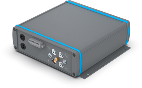
ELECTRO-PNEUMATIC UNIT
MOBILE AN INDEPENDENT
Our clamping and braking elements in particular provide high clamping forces with a low volume consumption and clamp just like our grippers or zero-point clamping systems as an NC variant when there is a pressure drop. The system bleeds as fast as lightning when the power fails thanks to our proven, integrated quick exhaust valve.
ELECTRO-PNEUMATIC POWERHOUSE
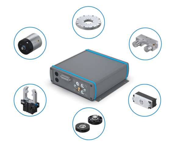
The electro-pneumatic unit can be combined with a variety of Zimmer Group products and enables the use of pneumatic products in areas where compressed air was previously not available. This opens up new possibilities in terms of design and safety and can offer a significant cost advantage.
INTEGRATED SENSING AND EXTENDABLE
The unit is specially optimized to our components with low air consumption and enables optimized and energy-saving use thanks to a dynamic pressure setting. A pneumatic pressure of between 4 and 6 bar can be selected, which is then reliably regulated and maintained thanks to integrated sensing. If you upgrade to pressure storage, this can help to reduce the process time even further.
LIGHT & COMPACT
At the same time, this light and compact unit can be positioned close to consumers, thus enabling very fast opening and closing times. Thanks to the simple control and 24V technology, our product is predestined for mobile units with a battery supply, such as driverless transport systems. In addition, various process sequences can also be implemented thanks to the controllable valves.
DESIGN INCLUDED
When integrating the electro-pneumatic unit with our components, we will be happy to offer you a design of the switching times – and for braking elements, also the calculation of the braking distance taking into account your application data.
ALL-IN-ONE POSITION SENSOR
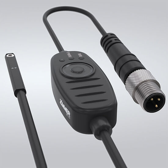
MFS02-S-KHC-IL
PRECISE and versatile
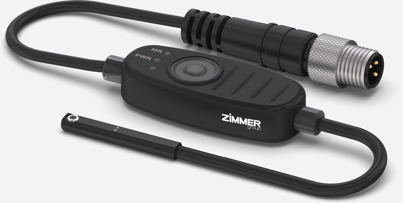
Discover our MFS02-S-KHC-IL position sensor. With IO-Link and an analog output, it extends our magnetic field sensor portfolio with continuous position measurement. The sensor features an impressive measuring range of up to 50 mm. With its space-saving installation in the C-groove, it can be integrated perfectly into any application. The exceptional resolution of 0.01 mm also enables the detection of defective parts (NIO), thus actively increasing your quality. Thanks to the dynamic teach-in function, which detects the standstill of the piston, three positions can be taught automatically.
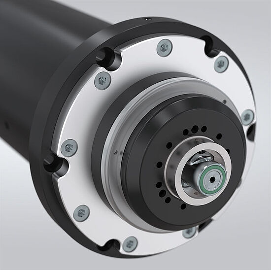
NEW MOTOR SPINDLES
Winner in all (performance) CLASSES
Extended product portfolio
The motor spindle is one of the essential components of a tooling machine, milling center or robot-based end-of-arm solution. The mechanically integrated motor solutions are extremely compact, highly productive and achieve maximum stiffness, which is required for the highest speeds and precise rotation. The Zimmer Group offers you the perfect product range for this.
Whether air or water cooled, optimized for low or high weight – the product range of motor spindles has been rounded off by the completion of the modular construction system in the lower to medium performance range. Whether you are looking for a motor spindle for use
in milling machines or machining centers, our spindle range includes economical standard motor spindles, air-cooled spindles in the lower and medium power range, fluid-cooled high-performance spindles and, of course, suitable accessories
from converters through cooling units, C-axes through to connection sets.
PRODUCT ADVANTAGES
- Air and water-cooled high-frequency spindles in a variety of output ranges
- Support on topics such as power dimensioning, energy supply, cooling or integration into the control system or service
- Repair and on-site service by expert staff
- Spindle I/O link communication module allows condition monitoring or predictive maintenance
- Extremely reliable, high performance density and high compatibility
SPN ZERO-POINT CLAMPING SYSTEM
ALL FUNCTIONS, ALWAYS AVAILABLE
GRIPPING IN ALL INDUSTRIES
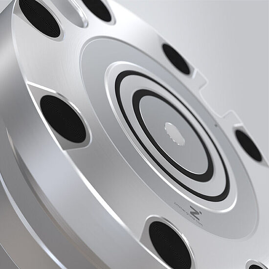
Securely locked with the modular zero-point clamping system from the Zimmer Group. In addition to a standard version that is reduced to the basic functions and fulfills the basic functions such as unlocking and PLUS connection, an extended version is available with a comprehensive range of functions as required in automated production. Both versions feature form-fit locking via clamp segments specially adapted to the screw contour, creating an extremely rigid system that can absorb strong forces with maximum repeat accuracy. The extended version also has a blow-out function, an integrated position control and a piston position monitoring, which can be done either pneumatically or electronically. With the SPN series, the Zimmer Group is consistently focusing on the mechatronics of its products in order to offer its customers electrically intelligent components at the highest level.
The product range is rounded off by a variety of clamping plates, which are available in every size and in different configurations. To increase the protection of the individual zero-point clamping system and prevent the ingress of dirt, an automatic locking system is available as an option.
Products Learn more

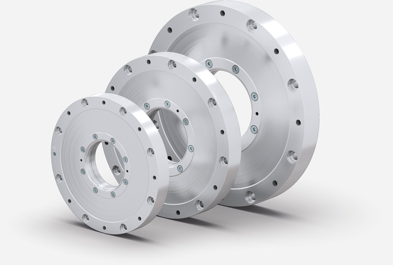
PNEUMATIC ROTARY CLAMPING ELEMENT
DKPS1000 SERIES
PNEUMATIC OR HYDRAULIC – THE CHOICE IS YOURS!
Increased performance requirements in tooling machines and an increased level of safety require powerful and innovative solutions. Following the successful market launch of our DKPS1000 series with pneumatic control and digital scanning, we are rounding off the extensive product range with additional installation sizes, thus closing the gap between all available sizes.
PRODUCT ADVANTAGES
- Torque absorption from shafts
- Safety clamping of the torque motor
- C-axis clamping
- Clamping and securing of swivel bridges
- Clamping of the spindle swiveling axis
SIMPLE STATUS SENSING
An efficient and fast process sequence is a requirement for all of our components and the DKPS1000 is no exception to this. The DKPS1000 can make use of its full potential thanks to the optional digital sensing. Additional safeties for switching times are no longer required.
HIGH HOLDING FORCES – WITHOUT ADDITIONAL AIR AND WITHOUT COMPROMISING CYCLE STABILIITY
The DKPS1000 series not only surpasses the non-pressurized holding force of rotary clamps available on the market; it also features an increased service life compared to the benchmark. Both of these properties equally ensure enhanced safety when it comes to safeguarding rotation and swivel axes. This also increases system availability.
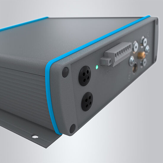
IO-LINK WIRELESS MODULES
ERROR-FREE communication
INTERFERENCE-FREE, SCALABLE, SECURE
Especially in robotics, the last robot axis often lacks an appropriate electrical interface for intelligent gripper components.
And in circulating systems, which are being used more and more frequently, it is missing completely. But why resort to external cable routing along the robot arm or circulation system and live with the associated disadvantages such as restricted freedom of movement, cable breakages and sources of interference when there is a straightforward solution?
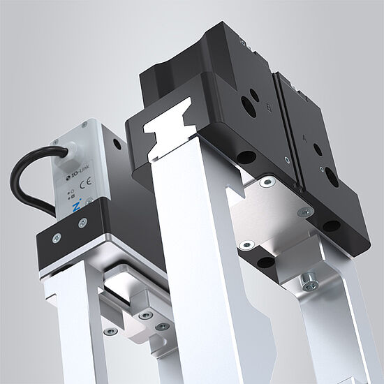
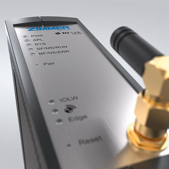
The standardized IO-Link Wireless communication modules from the Zimmer Group enable trouble-free and secure communication of IO-Link signals, without any cabling, and guarantee wireless transmission of all required signals and information.
